Using the Propeller Activity Board
Using the Propeller Activity Board
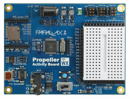
The Parallax Propeller Activity Board WX (or original, #32910) is a low-cost yet fully featured Propeller development board. It can be used to build any of the Kickstart demonstration projects or Propeller C tutorials, and includes a mini solderless breadboard, expanded I/O headers, and both 3.3V and 5V power regulators.

Because the solderless breadboard is integrated into the board, most of your projects may be completed using only short jumper wires, such as the 100mm Male-Male Jumper Wires – 20 Pack.
Providing Electrical Power
The Propeller Activity Board (original or WX) may be used with or without a separate power supply:
- USB cable. During programming and testing, power may be derived from your computer via a USB cable. Note that on most PCs, USB ports are limited to supplying no more than 500 mA (milliamps) of current. This is sufficient for running basic sensors and other components, but not servo motors and other high current devices.
- Separate power supply. When untethered from your PC, power may be derived by using a 6-9 volt battery pack, or a power adapter capable of delivering at least 1 amp at 6 to 9 volts.
Using the 3-Position Power Switch
The Propeller Activity Board (original or WX) uses a 3-position switch to control the distribution of power to the connector pins surrounding the solderless breadboard:
| Position | What it Does |
| 0 | Removes power to all power pin connections. |
| 1 | Applies power to the power pins over the breadboard, but not to the six servo headers along the top. |
| 2 | Applies power to breadboard pins, as well as the servo headers. |
Use the servo headers for fast and easy testing of the Parallax continuous or standard servo motors. Refer to the Propeller Activity Board (original or WX) documentation additional information.
Adapting the Breadboard Wiring Diagrams in KickStarts
You may readily adapt any Kickstart Propeller-based wiring diagram for use with the Propeller Activity Board:
- For Kickstarts with a Propeller Board of Education (BOE) breadboard connection diagram, merely follow the diagram as-is.
- For Kickstarts with a Quickstart and separate breadboard connection diagram, match the pin numbers (e.g. P0, P1, etc.) on the Quickstart board to those on the Activity Board.
- Use any available power (5V or 3.3V) and GND (ground) header pins to connect to power. (On the Quickstart board, VDD=3.3V, VSS=Ground, Vin=5V.)
If you use the power pins along the top and bottom of the breadboard, be sure to set the power switch to Position 1 or Position 2.
- Copyright: Creative Commons 3.0 SA license
