The number of times per second the BASIC Stamp checks the QTI sensors is an important consideration for line following. If a given PBASIC program doesn’t take enough samples per second, it means it’s waiting too long between samples, which can cause the Boe-Bot to miss a sudden change in the line’s direction, or even lose the line altogether. On the other hand, if the program devotes itself entirely to checking the line, there might not be enough time for the BASIC Stamp to check other sensors. By studying the relationship between sampling rate and line following performance, you can determine the minimum sampling rate necessary to navigate a course with a certain set of features. You can then use whatever time is left to check other sensors.
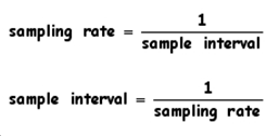
The rate at which a microcontroller checks a sensor is commonly referred to as ‘sampling rate’ and it’s typically expressed as a number of samples per second. The sample interval is the amount of time between each sample, which is expressed in terms of seconds. In cases where the sample interval doesn’t change, it’s called a constant sample interval. When the sample interval is constant, the sampling rate is just the reciprocal of the sample interval, and vice versa.

Frequency and Period Notation
Some documents refer to the sampling rate as a frequency (f) and quantify it in terms of Hertz (Hz). You might also see the sample interval expressed as a period (T) in terms of seconds (s). The sampling rate and sample interval equations for a constant sample interval would then be expressed as:

For example, you might see the sampling rate of ten thousand samples per second expressed as f = 10 kHz, and its corresponding sample interval would be T = 100 μs.
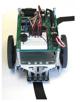
There are quite a number of adjustments that can be made to existing QTI example programs to make them more efficient and improve their sampling rates. One of the most important changes involves reducing the amount of time it takes to check the QTIs. This activity introduces a subroutine for reading multiple QTIs that takes very little time and is especially reliable for detecting black vinyl electrical tape on a white background (see Figure 1 below). This activity also features a line following example program that uses a subroutine to follow a line with four QTIs.
Figure 1 – Fully Assembled Boe-Bot and QTI Line Follower AppKit

Getting Started
This project contains advanced topics, not intended for Boe-Bot beginners. Before continuing, it is highly recommended you complete the following tasks in order to gain a better understanding on how this application works:
- Complete all activities in Robotics with the Boe-Bot (#28125).
- Download the documentation for the QTI Line Follower AppKit (#28108) and follow all instructions listed.
Source Code
Source Code for Line Following with Four QTI Sensors
(1) Boe-Bot Robot, assembled and tested (#28132)
The parts below are included in the Boe-Bot Robot kit:
(1) Piezospeaker (#900-00001)
(1) QTI Line Follower AppKit (#28108)
The parts below are included in the QTI Line Follower AppKit:
(4) 3-pin Male-Male Headers (#451-00303)
(4) QTI Sensor Modules (#555-27401)
(4) 3/8” 4-40 pan-head screws (#700-00016)
(4) 7/8” 4-40 pan-head screws (#710-00007)
(4) 1” round standoffs (#700-00060)
(4) 1/2″ round spacers (#713-00007)
(4) Nylon washers
(4) 10” servo cable extenders (#805-00011)
For this activity, you will also need to supply your own:
#2 Philips-head screwdriver
Black ¾-inch electrical tape
White poster board
Source Code
Source Code for Line Following with Four QTI Sensors
Source Code for Line Following with Four QTI Sensors
