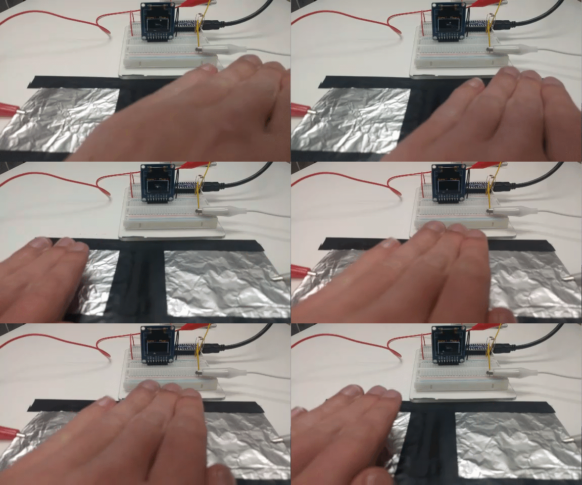
Aluminum foil is a low-cost and effective material you can use to create a capacitive touch sensor. This project shows you how to build and program a capacitive touch sensor circuit with an OLED color display to play the Blockly version of the game Pong. This program will work by calibrating a range of R/C time decay values the foil produces, then uploading the calibration into the main project. Let’s jump in!
Build It
The Pong game consists of two separate programs. The first being a calibration program to scale and constrict the R/C time values that the foils produce, and the second being the main game code. Note that the size of the aluminum foil squares can vary and work well up to around 12” x 12” as long as both are equal in size.
Pin Connections
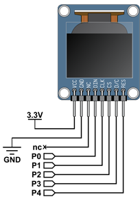
- P0 – P4: OLED display module
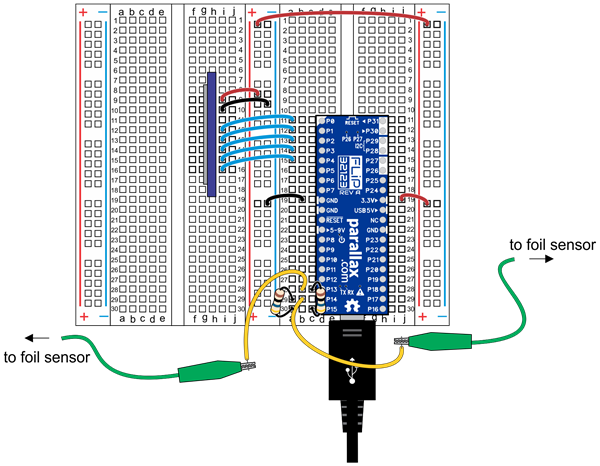
- P13 – P15: 10 MΩ resistors and alligator clips
Circuits
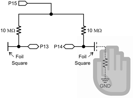
Build the circuits shown below, following the wiring diagram and schematics. Each alligator clip attaches to one foil sensor.
Double check to make sure the OLED display is wired correctly, and the aluminum foil sensors are not overlapping but are directly adjacent to each other.


Included in the FLiP Try-it Kit (#32023):
- (1) – USB A to Micro B Cable (#805-00016)
- (1) – Breadboard for the FLiP Try-it Kit (#700-32023)
- (1) – Propeller FLiP Microcontroller Module (#32123)
- (2) – Alligator clips (#800-00042)
- (2) – 10 MΩ resistors (brown-black-blue) (included in kits produced after Aug 07/2017)
- Misc Jumper Wires
Not included in the FLiP Try-it Kit:
- (1) – 96 x 64 Color OLED display module (#28087)
- (2) – 2” x 2” aluminum foil squares
- Tape
Pin Connections
- P0 – P4: OLED display module
- P13 – P15: 10 MΩ resistors and alligator clips
Circuits
Build the circuits shown below, following the wiring diagram and schematics. Each alligator clip attaches to one foil sensor.
Double check to make sure the OLED display is wired correctly, and the aluminum foil sensors are not overlapping but are directly adjacent to each other.


